Many peripheral devices are connected to the ESP32. So the ESP32 has to be placed and the connections organized.
Important. The pinout and the printed circuit board version 1.3.2 given below apply to the ESP32 DevKit V1 30 pin. For LILYGO T-Relay 4 (the environment
Samovar, the board is selected in the configurator) and ESP32-S3 (the environment
Samovar_s3) use the pinout from
Samovar_pin.h; the 1.3.2 board does not physically fit them.
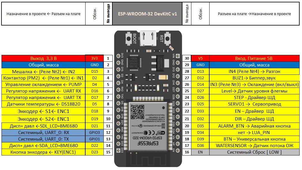
ESP32 pin limitations. The GPIO34–39 pins are input-only and have no internal pull-ups: for the emergency button (D35), the universal button (D39) and the flow sensor (D36) an external 10 kΩ resistor to 3.3 V is mandatory, otherwise there will be false triggering and an emergency stop right after power-up. These resistors are already provided on the printed circuit board. Run the wires to the flow sensor separately from the heating element power cables. Pin D15 (relay No. 2, stirrer) is pulled up in hardware at reset — the relay on it switches on briefly at every boot; use an active-low module, the relay polarity is set in the Samovar settings (relay 1–4 fields). The I2C bus pull-ups (display, pressure sensor, I2CStepper) are 4.7–10 kΩ.
Using the printed circuit board.
A special printed circuit board was developed for using the ESP32_30pin with Samovar. The following is installed on it:
C3, C4 - electrolytic capacitors 500 µF × 16 V (or 1000 × 16)
Note
The recommendations give values with a large voltage margin. With a voltage margin, even a not very good electrolytic capacitor will last longer and work more reliably.
But if you want to and are sure of your components, you can:
rate C1, C2 for 16 volts
C3, C4 - for 6.3 volts.
Resistors: R1-R3 = 10 kΩ, R4 = 4.7 kΩ . All 0.125 watt.
-
connection connectors. (note: some of the connectors can be left out and the wires soldered directly.)
It is recommended to install all the elements on the board right away: the buzzer, the atmospheric pressure sensor, resistors and capacitors, the pin header for the stepper driver, switches and connectors. Even if you do not plan to use some of the equipment at the moment. Later this will make it much easier to expand Samovar's capabilities.
Mounting locations and elements:
-
ESP-WROOM-32 mounting location for the ESP32. It is recommended to install it on a pin socket (female) connector
-
BME680 A place to connect an atmospheric pressure sensor (BMP180, BMP085, BMP280, BME280, BME680).
-
DS18B20 connection of temperature sensors. On the right (on the board) is a 4.7 kΩ power pull-up resistor for the sensors.
-
STEPPER - connection of the NEMA17 stepper motor of the peristaltic take-off pump. On the right is the place for the stepper driver.
-
SW1 and H1 - stepper step divider and additional control of the stepper driver
-
ALRM_BT Connection of the emergency button and emergency sensors.
-
LCD - connection of the LCD2004 display (no other display is supported)
-
ENC1 - connector for the encoder with a button.
-
-
WATERSENSOR - cooling flow sensor connector
-
BTN - multifunction button
-
SERVO1 - connection of the servo drive of the fraction selection table
-
PUMP - cooling pump control
-
LEVEL - connection of the reflux level sensor
-
BUZ1 - 3 volt active buzzer
-
DC_DC_5V - 12 to 5 volt voltage converter.
-
-
C1, C2 - electrolytic capacitors 500 µF × 25 V (or 1000 × 25)
-
C3, C4 - electrolytic capacitors 500 µF × 16 V (or 1000 × 16)
-
All resistors are 10 kΩ, except one 4.7 kΩ resistor
Where to get the board?
-
Ask in the support thread. Perhaps someone who has already built one has a spare and can share it.
-
Order it yourself.
The developed board is hosted on easyeda.com. At the moment it is not possible to order manufacturing through this service. But you can use the service.
For manufacturing we need the files in Gerber format, which is a description of the printed circuit board project for manufacturing.
The Gerber archive for manufacturing of the printed circuit board version 1.3.2, as of September 2024, can be downloaded from this link from our server.
Or:
Go through the menu: File>Generate Gerber file for production... (in the Russian-language easyeda interface: «Файл>Генерировать Gerber-файл для производства...»)
Click, and after the check prompt choose: "No, generate Gerber file" («Нет, генерировать Gerber-файл»), a window will appear
You can change:
- the number of boards - a multiple of 5 (you cannot order fewer than 5).
- the solder mask color - this is the color of the board. Choose green or blue. Other colors may cost extra.
Click generate Gerber. The created file will be saved to your computer as a zip archive.
Now you need to order manufacturing.
There are plenty of services that manufacture and, most importantly, ship. For example nextpcb.com there are instructions on the site or on the internet, payment via AliExpress.
Or go straight to AliExpress and type in the search "custom printed circuit board manufacturing". Seller offers will appear. Choose by reviews.
The ordering principle is the same - you send the seller the whole Gerber archive (if the file name is in Cyrillic - rename it to Latin). The seller determines the price and tells you. If it suits you, you pay - and in about a month you have the printed circuit boards.
The cost of 5 boards with delivery is approximately 15-20 USD.
Using a breadboard (shield)
The shield already has a 16...6.5-5v power converter and USB connectors - 5 volt power. The ESP32 is inserted into a female pin header, and the peripherals are connected to the pins (male header). All wiring has to be done with wires; the resistors and some of the capacitors are soldered either on the shield itself or on the enclosure connectors.
Using a shield is a decent solution, and quite inexpensive. But for the final assembly it is highly desirable to solder all wires rather than leave them on detachable connections, otherwise failures will follow one after another.
Shields are also made for ESP32_38 pin. boards, which lets you use an ESP32 with 38 pins too.
Using a soldering breadboard.
You can use a printed prototyping board designed for soldering components. (A printed circuit board prototype, breadboard, universal board)
All the elements can be placed on such a board, and there will even be room left for future upgrades. But working with such a board requires certain skills. A warning - building a Samovar on such a board is not exactly easy.
Nevertheless, the project can be implemented this way.
An example of building Samovar on such a breadboard:
Assembly without a board
And finally the last option - without any printed circuit boards. Point-to-point wiring.
A label with the pin designations is printed on a printer and glued to the underside of the ESP32, which is turned upside down and screwed to the enclosure on standoffs (for cooling). The wires are attached to the ESP32 pins with connectors such as Dupont.
An example of an implementation:
Recommendations:
- Having a printed circuit board makes assembly and the subsequent setup much easier. But most importantly, it spares you most of the problems caused by possible mistakes and poor connections between the ESP32 and the peripherals.
- If you want to start building, but nobody has shared a special printed circuit board and you do not want to order manufacturing yourself - using a shield is the most acceptable option.


